
Hydraulic overload oil pumps serve as the core ultimate safety protection components for mechanical punch presses. Their primary function is rapid pressure relief upon overload during stamping, material jamming, or foreign object intrusion into the die, so as to protect the crankshaft, connecting rod, machine frame and die against high pressure damage. Under the operating conditions in India and Egypt — featuring high ambient temperature, heavy dust, unstable power grids and aging equipment — overload oil pumps rank among the hydraulic components with the highest failure rates and are highly susceptible to mis triggering. Most on site factories face two critical thorny issues: unprovoked pressure relief during normal production, which results in insufficient stamping force, workpiece scrapping and production line interruption; and failure to release pressure under overload jamming conditions, which may trigger severe equipment accidents including crankshaft distortion, connecting rod fracture, die bursting and frame deformation. Most maintenance personnel cannot tell whether faults stem from improper parameter setting, oil contamination, seal aging, spool jamming or working condition mismatch. They blindly replace pumps and spare parts only to suffer recurring failures. This paper summarizes a practical set of diagnosis, repair and maintenance solutions for tropical workshop conditions, enabling fast root cause identification. The solutions are compatible with the full range of conventional J21 and J23 series mechanical punch presses.
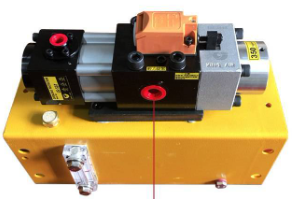
1. The real cause of frequent false pressure relief of the overload oil pump (pressure drop during normal stamping)
False pressure relief, also defined as pseudo-overload, refers to a faulty condition in which the equipment operates without actual overload, the sheet metal thickness remains standard, and no foreign matter exists inside the die, yet the oil pump automatically performs depressurization and pressure drop. This issue causes the sliding block to operate weakly and results in insufficient stamping force. Over 90% of such faults are not caused by oil pump damage, but by mismatched parameters and operating conditions, which are extremely prevalent in tropical workshop environments. First and foremost, the calibrated pressure value is set excessively low. Affected by long-term high-frequency equipment vibration and high-temperature thermal expansion and contraction, the overload pressure adjustment screw gradually deviates from its original position. The initially calibrated safe pressure value decreases continuously, causing the equipment to trigger pressure relief protection under normal stamping loads and resulting in irregular pressure drop failures.
The second root cause is slow leakage induced by high-temperature-driven seal aging, a frequent failure in tropical stamping workshops. Conventional rubber sealing components tend to harden, undergo minor deformation and lose elasticity under prolonged exposure to high-temperature environments. This leads to invisible internal slow pressure leakage inside the oil pump, which cannot be observed with the naked eye. Pressure readings remain normal when the equipment is unloaded and stationary. Nevertheless, once material stamping commences and oil pressure rises, pressure will slowly decay and trigger pseudo-overload. This fault manifests as intermittent misoperation with unstable performance, making it extremely difficult to troubleshoot.
In addition, air intake within the oil circuit, contaminated hydraulic oil, and slight spool wear may also bring about false pressure relief. Following on-site oil replacement and disassembly maintenance, incomplete exhaust leaves trapped air inside the oil circuit. This causes erratic hydraulic pressure fluctuations, whereby even minor pressure swings can activate pressure relief. Failure to replace hydraulic oil over long periods renders the oil turbid and mixed with fine metallic particles. These particles abrade the spool mating surfaces, resulting in inadequate high-pressure locking and unintended pressure relief under loaded conditions. Long-term high-temperature fatigue of the pressure-regulating spring, accompanied by elasticity attenuation and pressure threshold drift, can also disrupt the protection logic.
2. High-risk fatal fault of the overload oil pump: “no pressure release” (loss of protection under overload conditions)
Overload without pressure relief ranks as the most hazardous equipment fault in stamping workshops. It constitutes a severe safety hazard and may easily lead to total equipment scrapping and serious safety accidents. The most frequent human-induced cause is arbitrary elevation of overload pressure. To avoid false pressure relief and boost production efficiency, many factories deliberately set overload pressure far above the equipment -specified standard value. Consequently, during sheet-metal overload, die jamming or machine stall under overload, the pressure still cannot reach the pressure-relief threshold, and safety protection becomes completely ineffective. Forced stamping will directly damage the crankshaft and machine frame.
Secondly, spool sticking and jamming occur. Iron filings, oil sludge and impurities originating from dusty workshops penetrate into the overload oil pump and build-up within the spool fitting clearance. This fully locks the spool and prevents it from opening. No matter how high the stamping pressure rises, the pressure-relief channel stays closed. The equipment becomes completely locked, and the slider can neither advance nor retract. Under such circumstances, if operators force-start the machine with inching operation, the connecting rod will fracture directly and the crankshaft will suffer distortion.
In addition, blockage of the pressure-relief oil circuit, skewing and jamming of the pressure-regulating spring, as well as carbon deposition of hydraulic oil, may all result in overload protection failure. If hydraulic oil remains unchanged for an extended period, accumulated sludge will clog pressure-relief passages and stop pressure from being released normally. Deformation, jamming and misalignment of the spring hinder its compression for pressure relief, ultimately bringing about complete failure of overload protection. This constitutes a high-risk fault that demands emergency shutdown for maintenance.
3.On-site 3-minute rapid diagnosis: Accurately identify the root cause of overload oil pump faults
Static pressure-holding test (for distinguishing internal faults): With the equipment unloaded without material feeding or stamping, manually build up pressure and maintain pressure. If pressure drops rapidly and triggers automatic pressure relief after a short static stand-by period, the fault can be directly attributed to the oil-pump body. Typical defects include seal aging, spool wear, spring fatigue and internal slow leakage, so external working-condition inspection is unnecessary.
Dynamic stamping test (for distinguishing external working-condition faults): The equipment maintains stable pressure without pressure drop under no-load conditions, yet depressurizes immediately once sheet metal is loaded for stamping. This is most probably caused by low pressure calibration, residual air trapped inside the oil circuit, over-thick sheet metal, or misaligned dies resulting in excessive load. Such issues stem from parameter adjustment and working-condition mismatch rather than oil-pump damage.
Intermittent and irregular faults (for distinguishing impurity-caused jamming): The equipment works normally intermittently yet suffers accidental false pressure relief without fixed patterns. Such faults are mostly triggered by slight spool jamming from workshop dust and impurities, or hydraulic-system pressure instability brought about by grid-voltage fluctuations. It represents a typical hidden fault occurring in tropical dusty workshops.
Complete jamming without pressure relief (high-risk fault determination): When the equipment locks up with material jamming and fails to perform pressure relief, the root cause is definitely spool jamming, spring misalignment, or severely over-limit pressure setting. Power supply must be cut off immediately and the machine shut down. Forced inching or forced startup operations are strictly forbidden to avoid fault escalation and total equipment scrapping.
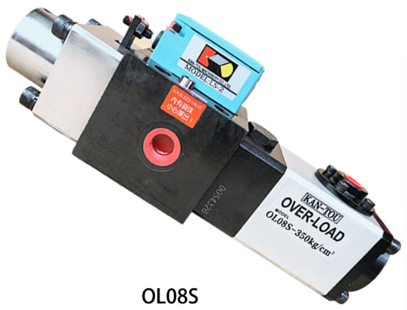
4. Specialized on-site repair solutions tailored for tropical working conditions
Precise pressure recalibration and parameter locking: Strictly set the overload pressure in accordance with the original-factory standard corresponding to the punch press tonnage; arbitrary increase or decrease is prohibited. After calibration, secure the pressure-adjustment screws and apply position marks. This counteracts parameter drift induced by long-term vibration and high-temperature offset of equipment, adapting the unit to continuous mass-production operating conditions.
4.2 Upgrade the high-temperature-resistant sealing assembly: For year-round high-temperature operating conditions in India and Indonesia, phase out conventional rubber seals and replace them with fluororubber seals featuring high-temperature resistance, anti-aging performance and superior elasticity. This thoroughly resolves slow-leakage and hidden pressure-relief faults caused by high-temperature aging, and greatly improves the pressure-holding stability of the overload oil pump.
4.3 Deep cleaning and maintenance of the oil circuit and valve core: Disassemble the overload oil pump to thoroughly clean internal impurities including oil sludge, iron filings and carbon deposits. Perform precision grinding on the contact surfaces of the valve core to ensure tight closure and reliable locking performance. Meanwhile, replace the equipment’s hydraulic oil with clean anti-wear hydraulic oil and renew the oil circuit filter elements. This eliminates internal impurities at the source and effectively prevents spool jamming faults.
4.4 Replacement of fatigued and aged components: Directly replace deteriorated pressure-regulating springs with weakened elasticity, deformation or rust, as well as all aging sealing parts with new components. This restores accurate pressure trigger logic, ensuring sensitive and precise overload pressure relief with zero action lag and zero failure.
Completely drain the air from the oil circuit: After every oil change and disassembly maintenance work, repeatedly carry out air flushing, pressure holding and pressure-relief cycles to fully evacuate trapped air inside the oil circuit. This eliminates hydraulic pressure fluctuations and prevents pseudo overload and misoperation.
5. Regular maintenance list to prevent recurring faults
5.1 Regular pressure calibration: Calibrate the overload pressure every 45 days in high temperature seasons; re-measure and verify it every 90 days under normal-temperature conditions. Promptly correct parameter deviations caused by high-temperature influence and mechanical vibration to maintain consistent accuracy of safety protection.
Strictly control the quality of hydraulic oil: Do not use turbid, inferior or expired hydraulic oil. Replace the oil and filter elements strictly on schedule to keep the oil circuit clean and reduce the probability of valve core wear and jamming.
5.3 Preventive replacement and maintenance: For high-temperature and dusty workshops, carry out advance replacement of the sealing assembly. Do not perform maintenance only after faults such as oil leakage, pressure drop or false pressure relief occur, so as to prevent risks of unexpected shutdown and workpiece scrapping.
5.4 Standardize the stamping production conditions: Forced stamping with ultra-thick plates, hard stamping with foreign objects inside the die, and long-term uneven load stamping are strictly prohibited. Reduce the frequency at which the oil pump operates under limit pressure, delay fatigue aging of internal components, and prolong the overall service life of the oil pump.